In the daily use process of curtain wall opening window, hardware system failure has become a common quality defect, and the overall falling off of the opening window caused by this will seriously affect public safety. In this paper, finite element simulation calculation is carried out on the system safety of with hooks opening window hardware & Specialties, and the influence of hardware system accessories under different working conditions on the overall safety of opening window is analyzed, at the same time, some specific suggestions are put forward to improve the safety of the open window. This article can provide some references for the design, installation, use and maintenance of glass curtain wall opening windows.
0 introduction
Common engineering quality problems of glass curtain wall opening window mainly include: glass outer piece falling off, opening window falling off as a whole, hardware system failure, etc. In the unit type glass curtain wall, the frequency of safety problems occurs in the open window of with hooks which is often used. There are two common forms of destruction: one is the destruction of the corner of the opening window profile, and the other is the overall shedding caused by the decoupling of the opening window. See Figure 1 and Figure 2 for the accident site where the opening window of a with hooks glass curtain wall falls off as a whole.

After investigation and analysis afterwards, the main reason for the opening window falling off was that the opening window was not properly locked at the construction site before the incident. Under the repeated action of strong wind, the connection between the opening window wind brace and Casement failed, the limiting effect of wind brace is lost. Repeated impact between the top of the opening fan and the beam causes the angle of the profile to break, which causes the opening window to fall off as a whole. Therefore, in order to ensure the safety of the with hooks opening window, we should do a good job in the structural design of the opening window hardware & Specialties system, control the construction and installation quality, and pay attention to the usual use and maintenance.
Based on the finite element analysis of the with hooks opening window hardware & Specialties system, this paper compares the influence of different hardware configurations on the safety performance of opening windows, and then provides some references for the design and construction of opening windows.
1 Computing model
The calculation model mainly analyzes the main stress components (including stopper and wind brace) of the hardware system in the open state, whether the mechanical properties under the design wind load and the self-weight load of the open window meet the specifications and design requirements.
1.1 Model material parameters
The materials of each part of the opening window are as follows: The Casement profile is aluminum alloy, and the interior is inlaid with hollow glass; The upper stopper is aluminum alloy material, and the brace is stainless steel material. The physical parameters of the material are shown in Table 1.
Table 1 material parameters
Material Name
Modulus of elasticity (GPa)
Poisson's ratio
Density (kg/m 3)
Yield strength (MPa)
Ultimate tensile strength (MPa)
Aluminum Alloy
68.9
0.33
2700
55.2
235
Glass
55
0.25
2600
/
/
Stainless steel
200
0.29
7900
310
620
1.2 calculation condition
In order to completely analyze the safety and stability of the structure, the structural calculation conditions are shown in Table 2.
Table2 calculation condition
Working condition no.
Working condition description
Description
One
Stopper and wind brace work properly
Wind brace stopper are installed correctly
II
Only stopper working properly
Wind brace damaged
Three
Stopper works normally, only one side wind brace works normally
One side is wind brace damaged
The calculation method of the model under each working condition is the first integral and then the local calculation method. Firstly, the whole open window model is analyzed first, and the elastic method is adopted for calculation. Gravity and design wind load are applied on the stress surface of the model, and the constraining force of each constraint is calculated. Then, the fine finite element model of stopper, the components on the retaining fan and the components on the frame is established, and the constrained reaction force obtained from the whole model is taken as the fine finite element model of load, and the elastic-plastic analysis is carried out. Finally, the bearing capacity and safety of the whole model are evaluated according to the elastic-plastic finite analysis results. The following specifically analyzes the bearing capacity of the main stressed parts of the hardware system that opens the window under each working condition.
2 Finite element analysis results
2.1 working condition 1: both the supporting block and stopper work normally
The overall model includes: Casement (including glass), Upper stopper, top hook, and bracing between window frame and Casement. The overall model is shown in figure 3.

The model adopts the mapping grid division method, and a total of 15770 units are divided. For the main model unit, the shell unit is used for simulation, and for the supporting parts on both sides of the lower part, the line unit is used for simulation. When the model is built, the short edge is arranged from left to right as X positive direction, the long edge is Y positive direction from bottom to top, perpendicular to glass surface and pointing out of the window as Z positive direction. After the model is established, boundary constraints are applied to the model. According to the actual working state of the model, constraints are imposed on the end of the supporting Rod, the upper stopper and the top hook respectively. 1) open window constraining force
Under the wind load of 2.19kPa and gravity load, when all the constraint ends work normally, the force at each constraint of the overall model is analyzed. According to the calculation, see table 3 for the constraining force obtained from the overall model under working conditions.
Table 3 Overall model constraining force
Constraining force
Reaction value/kN
Upper stopper reaction force
1.67
Y-direction reaction force of lower support and support rod
1.28
Z-direction reaction force of lower support rod
2.11
The obtained constraint reaction force is added to the components on the support fan, the components on the frame and the stopper model, and the elastic-plastic analysis is carried out to judge the working conditions of each constraint part. 2) stopper analysis the overall model adopts free partitioning method to divide the grid, with a total of 4000 units, and the entity part adopts the entity unit. The three fixed screw holes on the model are constrained as the constraint condition of the model, and the load on the bottom of the previous stopper is loaded to the lower projection of the stopper. Considering that the stopper is not the whole stress of the lower part, the load is only applied on the unit node of half the length of the lower part to simulate the real contact between the stopper and the open window. After the model is established, the elastic-plastic analysis method is adopted to analyze the deformation and stress of the model after being stressed. The calculation results are divided into displacement vector and equivalent plastic stress, which are shown in Figure 4 and Figure 5 respectively.
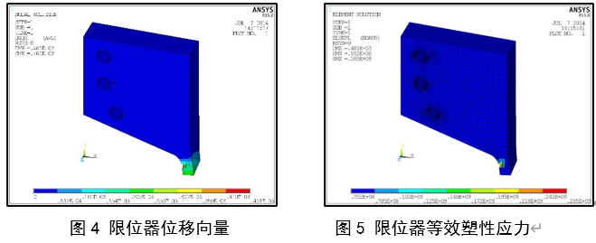
From the calculation results, it can be seen that the displacement of stopper mainly occurs in the stress part of the end, and the maximum displacement is 0.46mm. It can be seen from the stress cloud diagram that under load, most areas are within the elastic range, and larger plastic stress only occurs within a small range of the force, the plastic stress development area accounts for about 1/2 of the width and is not connected. Therefore, stopper is safe. 3) analysis of upper parts of supporting and retaining fan
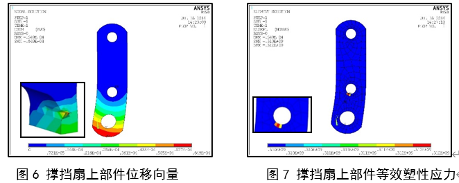
The whole model adopts free partitioning method to divide the grid, with 224 units in total, and the solid part adopts shell plane units. The two fixed screw holes on the model are constrained as the constraint condition of the model, and the load at the end of the support Rod obtained before is loaded at the lower connection hole. Considering that the connecting hole is not full-hole force, the load is only applied on the semicircle regional node in contact with the supporting Rod, in this way, the contact between the parts on the support fan and the Casement is simulated.
After the model is established, the elastic-plastic analysis method is adopted to analyze the deformation and stress of the model after being stressed. The calculation results are divided into displacement vector and equivalent plastic stress, as shown in Figure 6 and figure 7 respectively. It can be seen from the displacement cloud diagram that the displacement is mainly concentrated around the loaded screw hole, and the farther away from the constrained screw hole, the greater the displacement, the maximum displacement 0.065mm. It can be seen from the plastic equivalent stress nephogram that under load, most areas are within the elastic range, and the larger plastic stress only occurs within the minimum range of the surrounding area of the middle screw hole, with the maximum value being 312MPa, and it is not connected. Therefore, it can be concluded that the components on the supporting fan are also safe.
4) analysis of components on the supporting frame
The main body floor model adopts free partitioning method to divide the grid, and the ribs and baffles on both sides adopt mapping partitioning method. After the division is completed, there are 2993 units in total, and the solid part adopts shell plane units. Impose constraints on the two fixed screw hole parts of the model, and relax the constraints of the region affected by tension in practice as the constraint conditions of the model, apply the load of the support rod obtained before to the unit node of the upper part stop dog of the support frame and the right part of the support frame which is equal to the length of the actual connection slider, respectively, in order to simulate the contact between the components on the supporting frame and the supporting rod.
After the model is established, the elastic-plastic Large Deformation analysis method is adopted to analyze the deformation and stress conditions of the model after being stressed. The calculation results are divided into displacement vector and equivalent plastic stress, and the results obtained after the final calculation are shown in figure 8 and figure 9 respectively.
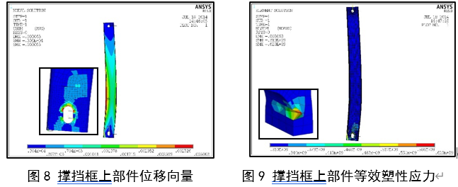
It can be seen from the displacement vector nephogram that the displacement mainly occurs at the edge of the stressed position and its relative rib plate edge, which is in the shape of force bending. The displacement decreases to both sides, and the maximum displacement is 3.063mm. After observing the plastic equivalent stress nephogram, it can be seen that under the load, most areas are within the elastic range, and larger plastic stress only occurs within the range of the surrounding area of the lower constrained screw hole, in addition, the plastic stress area develops upward, most of which have small plastic stress and concentrated large stress in a small local range, but they are not through, so the components on the bracing frame are also safe. 5) result analysis
From the elastic-plastic analysis results of each component, it can be seen that the stress of each component does not exceed the ultimate tensile strength when the upper two sides stopper and the lower two sides of the bracing block work normally, although the plastic stress zone appears locally, the stress zone is not connected and the stress does not reach the ultimate strength. Therefore, the overall structure is safe.
2.2 working condition 2: only the upper stopper works normally
Although the overall safety and stability of the structure are improved after the installation of stopper, in the actual service process, the upper stopper and the lower bracing can basically not play a role at the same time, this also leads to the occurrence of destruction and cannot be at the same time. Therefore, it is necessary to analyze the overall situation of the structure when only the upper stopper continue to serve after the two supporting blocks in the lower part are damaged.
1) only the stopper of the overall model of the open window under the working condition of the upper constraining force
Analyze the size of the overall model binding force when only the upper stopper is constrained under the actual wind load and gravity. According to the calculation, the stopper constraint force generated by the overall model at the constraint of the lower support rod is 23.43kN, which is applied to the window frame through a protruding block in the upper part of the window frame, in turn, force is applied to the open window model.
Add the obtained constraint reaction force to the stopper model and conduct elastic-plastic analysis to judge the working conditions of each constraint part.
2) stopper analysis
The mechanical analysis model here is the same as before and only changes in load size. The elastic-plastic method is adopted for calculation and graded loading is adopted, which is divided into 10 levels. When the load is loaded to step 2, the calculation does not converge. The calculation results of step 1 are shown in Figures 10 and 11.
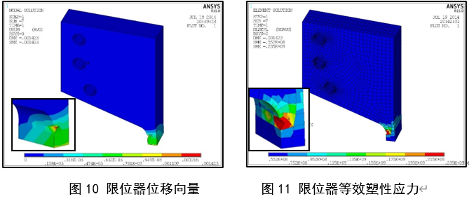
The maximum displacement in the displacement vector nephogram is 1.423mm, which is mainly concentrated on the edge of the contact position between stopper and the form, which easily leads to separation between the two. It can be seen from the plastic equivalent stress nephogram that under the second state of working condition, plastic yielding is easy to occur at the bottom stopper of the frontier area. When the yield failure occurs, the stopper will lose its constraint ability, which leads to the general demolition of the open window model.
3) result analysis
After the above calculation, it can be found that when the lower support block fails or cannot work normally due to installation reasons, or the lower support block is damaged successively, the stability of the whole open window model is completely maintained by the stopper on both sides of the upper part. Through calculation, it is found that the bottom edge of the stopper is prone to yield failure and plastic deformation. On the one hand, the stopper itself cannot continue to restrict the opening window due to the failure of its own strength. On the other hand, when the plastic deformation increases to a certain extent, the contact between the stopper and the opening window becomes extremely unstable, separation easily occurs, thus losing the ability to restrain. Through the above calculation and analysis, it is shown that the structure can not continue to serve at all. And because the total load is 2.34kN, when the load on the stopper exceeds 4.69kN, the stopper will be damaged.
2.3 working condition 3: The upper part stopper works normally, and the lower support block is only in the normal working state on one side.
Under the normal installation State of the upper stopper, the lower support restraint may cause one side of the support to fail due to installation errors or use wear, this causes the lower support restraint to generate a state in which only one side is working normally. In this state, whether the unilateral retaining constraint can maintain the safety and stability of the open window is the main problem of the three working conditions.
Under the action of wind load and gravity, when the upper stopper is installed normally and the lower right bracing block is unilateral normal working state, the force at the constraint of the overall model is analyzed. According to the calculation, the binding force generated by the whole model at the right side of the lower end of the supporting Rod and the constraint of the stopper is shown in Table 4.
Table 4 overall model constraining force
Counterforce position
Reaction value/kN
Upper stopper reaction force
11.07/0.47
Y-direction counterforce of right-side support rod
2.07
Z-direction reaction force of right-side supporting Rod
3.43
Due to the normal operation of one side of the lower support block, the overall open window model constraining force is asymmetric, so the stopper constraining force values on both sides of the upper part appear asymmetric phenomenon.
According to the previous conclusion, when the load applied on the stopper exceeds 4.69kN, the stopper will be damaged, and at this time, the load applied on the left stopper has reached 11.07kN, therefore, in this process, the left stopper first destroyed. When the stopper on the left side is destroyed, only the support rod on the right side and the constraint on the right side play a role in the open window model. The constraint reaction value at this time is counted in Table 5.
Table 5 stopper after the destruction of the left constraining force
Counterforce position
Reaction value/kN
Right side stopper reaction force
0.57
Y-direction counterforce of right-side support rod
2.75
Z-direction reaction force of right-side supporting Rod
4.55
When only the right support block and the right stopper constraint are left, compared with the working condition, it can be seen that the force on the support block constraint has exceeded the force on the support block damage, therefore, the supporting block will be damaged accordingly. After that, only stopper on the right side was left, and the damage soon occurred. Therefore, the final destruction sequence is the first destruction of the left stopper, which leads to the destruction of the right bracing block and the final destruction of the right stopper, this is the failure sequence and mechanism of the open window model under the three states of the whole working condition.
Based on the calculation and analysis results under the above three working conditions, the following conclusions can be drawn: Firstly, under the condition of stopper reinforcement and normal operation, due to the constraint effect of stopper, however, the load on the components on the support fan and the components on the frame is further reduced, thus improving the safety of opening the window. Secondly, when the lower support block fails or cannot work normally due to installation reasons. Through calculation, it is found that the bottom edge of stopper is prone to yield failure and plastic deformation. Finally, further calculation shows that if only one side of the lower bracing block is in normal working state, the constraints of the window will be destroyed, thus making the window become a mechanism and there is a risk of falling off.
3 Conclusion
For with hooks opening windows, reasonable design and accurate installation of hardware system are very important to ensure the overall safety of opening windows. This paper puts forward the following suggestions:
1) for the existing glass curtain wall open window, the anti-fall hinge can be additionally assembled to improve the overall safety of the open window.
2) for with hooks open windows with a height greater than 2m, 2 pairs of stopper can be set on each side to prevent safety accidents that unhook the open windows and fall off as a whole.
3) open the connection part between window profile and hardware, and do partial thickening treatment, and choose high-quality fasteners at the same time to ensure the strength of the connection part.
4) the maintenance of opening windows should be strengthened at ordinary times, and the quality problems existing in opening window hardware & Specialties system should be dealt with in a timely manner.
Author Li Cong Zhang Xichen
References
[1] China Academy of Building Sciences. JGJ102-2003 technical code for glass curtain wall Engineering [S]. Beijing: China building industry Press, 2003.
[2] China Academy of Building Sciences. GB50009-2012 load code for building structures [S]. Beijing: China building industry Press, 2012.
[3] China building metal Association. JGJ214-2010 technical code for aluminum alloy doors and windows Engineering [S]. Beijing: China building industry Press, 2010.
[4] China building metal Association building doors and windows accessories Committee. JG/T126-2017 building doors and windows hardware Drive Lock device [S]. Beijing: China building industry Press, 2017.
[5] China building metal Association building doors and windows accessories Committee. JG/T128-2017 building doors and windows hardware support block [S]. Beijing: China building industry Press, 2017.